After a great deal of planning, I’ve finally begun work on building an indoor, electric brewery. The plan is for a three-vessel, 5-gallon HERMS system.
The first task is to build the brew stand. This is a fairly short unit made to hold all three vessels, with the hot liquor tank elevated to allow gravity sparging if desired.
The lower tier is 25 in from the floor, and the upper is 40 in. The bottom shelf is at 7 in: high enough to clean beneath it and to avoid minor basement flooding.
Materials
The shelves are built from 2x4Basics shelving brackets. These hold four 2x4’s side-by-side to make each shelf, with 2x4’s comprising the vertical supports. The resulting shelves are about 16 in. wide. The manufacturer claims to support 1000 lb over 8 ft spans. To be safe, in this build each vessel is supported on its own 2 ft span. This system can easily accomodate the very uneven floor in the basement.
The lumber is 8 ft 2x4 studs, since that’s the length that fits in my car. I selected a “premium” grade, which looks a bit better. Treated lumber seemed risky with high heat, and anyway isn’t very attractive.
Calculating the required board lengths is a little tricky, as some of the horizontal pieces butt up against the verticals while others continue on through. This build required 13 studs, cut to six different lengths.
Results
The completed brewstand looks like this:

You can see some hint of the uneven floor by the line between gray and white behind the stand. The stand is set 16 in from the wall to avoid the uneven floor and the gas meter, and even so the leg lengths differ by almost 2 in.
The shelves are not as deep as I had expected, and the 18 in diameter pot hangs about an inch off the front and back. However, the unit is very stable and even when the vessels are filled with liquid, there’s no danger of tipping.
In the upper right, you can see the electric supply. Here’s a closer view:
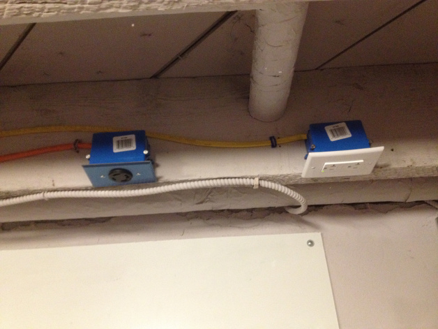
On the left is a 30A dedicated 240V L4-30R, protected by a GFCI breaker. While I won’t get into the basement rewiring project here, it’s worth mentioning that this is just about the most expensive way I could have set up a GFCI-protected 30A circuit. The breaker itself was over $120! The cheapest option seems to be a “spa panel” with a 50A GFCI breaker built in. Although these panels have a reputation for failing frequently, they cost around $60, so after buying two the cost is still even!
On the right is a 20A dedicated 120V L5-30R, with GFCI in the receptacle itself. In the final build, this will likely be used for utility purposes only, as the 30A circuit should be able to run one element and both pumps alone.
Next Steps
Next up is a simple switchbox for controlling power to the pumps and a very manual controller for the heating elements. This, along with a brew kettle and installation of the elements, should be enough to get me brewing again. Then I can get a better feel for the strengths and weaknesses of the system before committing to full automation.