I’ve been working on the system in spare moments, preferring to get things done rather than sit at the terminal writing blog entries. I just finished a brew on the new system, but for the moment let’s pretend that date is still to come.
Aside from pumps, connected to the pump controller described in the previous post, the brewery has two electric heating elements that must be controlled safely. One, in the hot liquor tank, is a 1500W, 120V element. The other is a 5500W, 240V element in the boil kettle. The power supply isn’t sufficient to run both elements simultaenously, so the controller ensures that at most one element is active at any time.
The hot liquor tank has a temperature controller, while the boil kettle is simply on or off.
The controller contains a keyed switch controlling all power, with a green indicator light. Next is a three-position switch controlling power to either element or, in the middle position, neither. The HLT control contains an STC-1000 temperature controller. The status of each element is displayed with a red indicator light.
Materials
- 2 x 8”x8”x4” PVC junction box - Lowes = $22 x 2 = $44
- Southwire 6’ ¾” Liquaflex Non-metallic Whip Kit - Home Depot = $10
- ¾” threaded cable gland - Lowes = $1
- 10A DIN-mount Breaker - oscsys = $5
- 25A SSR - Amazon = $12 w/ sink
- SSR Heat Sink - included
- STC-1000 temp controller - have
- 2P 63a DIN-mount contactor - oscsys = $25
- 1P 25A DIN-mount contactor (extra pole unused) - oscsys = $16
- L14-30P twist-lock - Amazon = $16
- 8’ 10-4 (H/H/N/G) SJOOW - Lowes = $16
- 8’ ½” expandable sleeving - Amazon = $4 (partial from 50’ lot)
- ¾” x 4” heat-shrink 2pk - Amazon = $1 (partial from 10’ lot)
- 3-way 10A switch - ebrewsupply = $5
- 2-way 10A key switch - ebrewsupply = $5
- Green 120V LED - ebrewsupply = $3
- 2 x Red 120V LED - ebrewsupply = $3 x 2 = $6
- DIN Rail - oscsys = $4 (12”)
- L14-30R twist-lock - Amazon = $19
- L5-20R twist-lock - Amazon = $15
- THHN Black / Green / Red / White 10ga stranded wire - Lowes = $18 x 4 = $76
- THHN Black / White 12ga stranded wire - Lowes = $15 x 2 = $30
- THHN Black / White 14ga stranded wire - Lowes = $15 x 2 = $30
- 4-terminal Ground Bar Kit - Home Depot = $5
- 7-terminal Ground Bar Kit - Home Depot = $5
Design
The controller has two main parts: the power controller and the interface controller. Each part is in a dedicated junction box. The two boxes are connected by a non-metallic, waterproof “whip” of conduit.
The original design had everything in a single junction box, but once the wires were in place, the available space proved inadquate. The split design has the advantage of putting all of the high currents and thick cables safely out of the way. The interface controller can move around as necessary.
Power Controller
The power controller takes the incoming two-phase power and splits it into three segments:
- Single-phase 240V power for the boil kettle element, controlled by a double-pole relay;
- 120V power for the hot liquor tank element, with the hot lead controlled by a relay and an SSR; and
- 120V power for the interface controller, protected by a 10A circuit breaker.
The circuit diagram looks like this:

The top portion controls the boil kettle element. This element has no neutral (although it uses NEMA L14-30 connectors, which have a neutral leg), but both hot legs are switched by the double-pole relay. This is a safety measure to ensure that when the element is off, there are no hot conductors at the boil kettle.
The bottom portion controls the element in the hot liquor tank. This circuit is between neutral and hot, and there is no need to switch the neutral leg, so only one pole of the relay is used. The relay controls whether the element is enabled, while the SSR allows the temparature controller to switch the element on and off as needed. Power only reaches the element when both are in the “on” position.
The “N” and numbers 1 through 6 denote connections to the interface controller via the whip. N and 5 supply breaker-protected power, 1 and 2 control the relays, 3 and 4 control the SSR, and 6 feeds back to the HLT LED.
Interface Controller
The interface controller contains the switches, lights, and the temperature controller.
The temperature controller is a modified STC-1000. Out of the box, this temperature controller contains a relay which closes when heating is required. This relay is only rated at 10A, so it cannot pass the element power directly. The power controller uses an SSR for this purpose, but the input to the SSR is 3-32VDC. Unmodiifed, this would require a transformer and rectifier to provide DC power, controlled by the relay, to activate the SSR.
On Ryan Hope’s advice, I opened the STC-1000 and found that it already contains a 10V transformer which drives the internal relays. I simply de-soldered the relay and connected its inputs directly to the screw-terminal outputs. With this modification, the STC-1000 provides 10VDC on its output, perfect for controlling the SSR. Sadly, I put the device back together without taking any pictures. If you’re interested in this modification, let me know in the comments and I will open it back up.
The interface controller circuit diagram looks like this:

The “N” and numbers 1 through 6 correspond to those in the power controller diagram. The switch at the top is the master switch, and controls power to the downstream switch, the STC-1000, and the green indicator light.
The three-position switch is at the lower left. Switched to the right, power goes to conductor 1 and activates the boil kettle element. In this position, it directly illuminates the red “heating” light. Switched to the left, it applies power to conductor 2, enabling the HLT element. The “heating” light for this element is only illuminated when the SSR is also switched on, by power fed from conductor 6.
As described above, the modified STC-1000 sends 10VDC on conductors 3 and 4 when heating is required.
The controls are laid out like this:

Build
The most significant lesson learned here is that DIN-mounted components are a nightmare to connect to.
DIN is a system for mounting multiple components side-by-side on a steel rail:

The rail itself carries no power; it’s just a mounting system. The devices have little spring-loaded tabs that allow them to clip onto the rail. They can be released by pulling the tab back with a flat-head screwdriver.
These devices look professional, and carry a professional price tag, but they’re cheap and flimsy. They don’t grip the rail very firmly, so they rattle quite a bit. The plastic bodies are weak, and all of the terminal screws are of different sizes.
In most internal wiring jobs like this controller, when multiple devices are connected together, they would be daisy-chained. That is, incoming power would connect to the first device and a second wire would lead from that connection to the next device, and so on. This works beautifully for devices with big, top-mounted screw terminals like the SSR here, or like all of the devices in the interface controller. The DIN-mounted devices, however, rely on pressure from the tip of a screw, and cannot secure a ring terminal. Any wiggling of a wire will pull it loose, and since the wires all enter at the bottom of the devices, wiggling is unavoidable as the device is clipped to the DIN rail beneath.
In the photo above, the middle device is the 25A relay, with the contactor connections at the bottom. Those holes are too small to admit the 12 gauge wire you would need for a 25A load.
Power Controller
Even without the switches and lights, space in the power controller is tight:
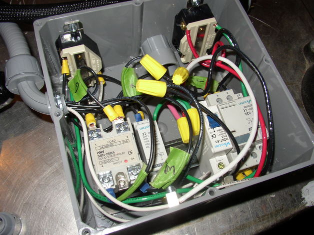
I managed to secure all of the connections by modifying spade terminals (crushing them with lineman’s pliers) and cranking down on the cheap terminal screws. But fitting two wires into any connection was out of the question.
For the non-hot conductors, I used ground bus bars, epoxied to the side of the enclosure, to bus together multiple devices. One bus bar is for neutral, and the other for ground. Using a bare neutral like this is a little sketchy.
The hot conductors are joined using regular residental wire connectors. This is unusual in device wiring, probably for good reason, but it works. Note that the hot leads are jumpered together, since there were more wires than would fit in a single connector.
The DIN rail is secured to the back of the enclosure using nylon stove bolts. The two receptacles are secured using metal stove bolts, since they connect to grounded parts of the receptacles. The power cable enters the enclosure through the round PVC fitting in the upper middle of this picture Although you can’t see it here, this too is using a metallic cable gland: I made the mistake of ordering non-metallic cable glands from an Amazon seller in China that promises to have them here by mid-April.
Waterproof Whip
The seven conductors threaded through the 6’ whip are all 14 gauge, except for the 12 gauge neutral. Together, they fill the whip completely. Pulling them through was difficult: I taped the wires together with a pull string, straightened the whip by clamping it to my workbench, and alternately pulled and shoved the wires through until they emerged from the other end. Each of the black conductors is labeled with some spare painters’ tape.
Interface Controller
Without the wiring:

Fully wired to the whip:

The interface controller’s wiring is a lot neater than that in the power controller. The spade bits and short jumpers between components are easy to put together and readily inspected for correctness. This is an excellent example of the daisy-chaining described above. I’ve used zip-ties with tiedowns in a few strategic locations to hold wires in place and to provide some strain-relief for the temperature probe wire (seen running out of the hole in the side of the enclosure).
It’s not obvious in this shot – in fact, it’t not obvious in person – but the front panel cracked during the wiring process. However, once the controller is fully screwed together, the crack doesn’t seem to cause any weakness in the controls.
Debugging
I performed a few spot-checks with a continuity checker before powering this project up. Then I manipulated the controls without any load applied, verifying the results using a multimeter.
I’m happy to say that everything worked without issue on the first try.
I was concerned about the heat load from the SSR. It is operating well below its rated capacity, though, and has now weathered two brew sessions with no more than a minor warming of the controller enclosure.